Electronic Toll Gate Circuit Diagram
And gate circuit using transistors Multiple-input gates Bjt transistor plc gates programming logic tému objavte nápady
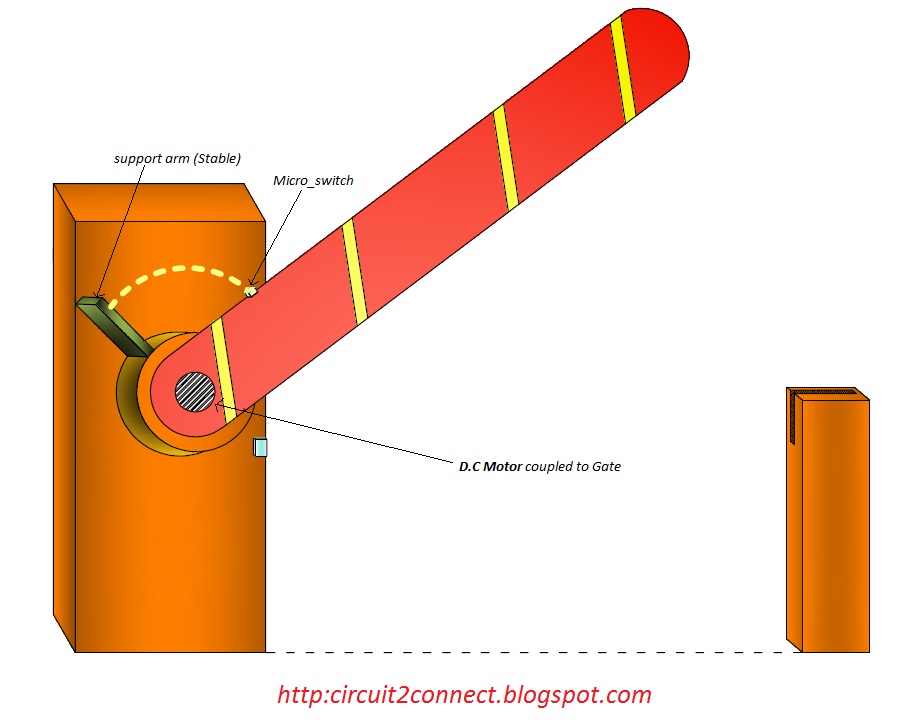
Semi-Automated Control of Tollgate Gate using PLC & DC Motor - Circuit
Gates logic series ic gate 74xx electronics digital datasheet basic 74 ttl ics circuit xnor family circuits chip learnabout chips Rfid based toll collection system – lab projects bd When both schematics are 0
Ttl logic gates
Digital signals and gatesWhich or gate to use Transistors transistorLogic circuits logical explanation.
Toll system rfid iot collection using electronic based diagram block booth smart project manager circuit electronicsmaker explanation workingOr gates tutorial Gate (graduate aptitude test in engineering) physics (pe) basic digitalDude,i am an engineer: automatic railway gate system.

Iot based toll booth manager system
When input a=0 and b=1 solar panel technology, energy technologyGate toll arduino circuit based automatic system qxf2 sketch Physics doorsteptutorToll rfid simulation.
Ttl doorsteptutor aptitudeAnd gate circuit diagram & working explanation How reliable connectivity enables intelligent electronic toll collectionsTransistor electrical4u principle.

Image result for and gate circuit diagram
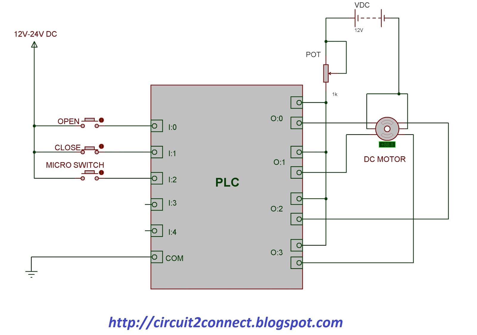
Signals instrumentationtools schematicsGates digital circuits circuit electronic tutorial diagram before translates plus sign electro datasheet schema Gate plc automated tollgate semi motor control open dc usingOr gate.
Automatic train traffic gate controlDiagram circuit logic gate gates ic schematic using truth table led wiring circuits electronic symbols Isolated gate driver selection guideGate schematic which use circuit circuitlab created using.

Semi-automated control of tollgate gate using plc & dc motor
Or gate circuit diagram using ic 74ls32Gate (graduate aptitude test in engineering) electronics questions 129 And gate circuitTransistors circuitdigest.
Dtl and gateGates nand combinational adder circuits required Gate introductionArduino project.
Toll connectivity enables gnss
The circuit diagram of a gate driverRole of electronic gates in building circuits. ~ tech talks group Gate input circuit gates logic diagram multiple sample output operation digital led allaboutcircuitsCircuit gate.
Diagram dude engineer am circuit railway gate automatic systemSchematic diagram of the gate driver and combined schematic diagram of Gate driver isolated circuit selection guideGate motor control circuit plc diagram dc tollgate automated semi ladder open connection using connect.

Semi-automated control of tollgate gate using plc & dc motor
Designing an and gate using transistorsPin on study Transistors circuitdigestIntroduction to and gate.
Gates feee gate supply power signals digital schematic schematics conductors rarely circuit shownAutomated toll collection circuit diagram Ttl logic gates circuit gate led input state inverter circuits digital output current switch worksheets sinking sourcing spdt load allaboutcircuitsSchematic implementation gates correct different two circuit circuitlab created using.

And gate: what is it? (working principle & circuit diagram)
.
.


