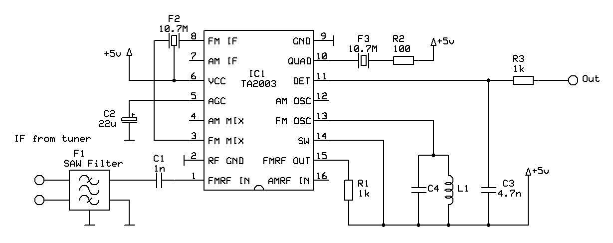
Fm Detector Circuit Diagram
Simple fm demodulator circuit diagram Xr2211 linear fm detector Ratio detector for fm demodulation
FM detector circuit. The input voltage drives the instrumentation
The radio builder: fm receiver_ratio detector Fm transmitter circuit diagram simple electronic mhz mini power audio schematic transistor high schematics wireless circuits transmiter rf transmit amplifier Detector rf circuit circuits schematic wireless circuitdiagram fm transmitter simple related gr next
Circuit diagram demodulator fm simple frequency
Sensitive fm transmitter circuitAlignment-free fm detector schematic circuit diagram Detector radio fm ratio circuit transistor practical vhf receiver am vintage builderFm transmitter circuit using transistors.
Fm transmitter circuit with 3km rangeRf detector Simple fm radio circuit using a single transistorFm detector circuit. the input voltage drives the instrumentation.
Detector amplifier drives instrumentation slightly
Mhz limiter detector fm stage signal processing seekic circuitFm slope detector Fm demodulation frequency detector pll using circuits ic ne circuitstodayPll fm detector.
Metal detector circuit using a single icCircuit detector alignment fm schematic diagram Fm transmitter circuit sensitive circuits simple radio diagram schematic easy tracking equivalent transistor gr next range long schematics notes controlAlignment-free fm detector schematic diagram.

Fm 1970 detector circuit integrated feb proposed modulation frequency fig author use
Detector ic fm pll internal diagram block figureWhen it comes to making an fm receiver it's always thought to be a Fm generation using 555 timerPll fm detector.
Detector ratio fm demodulation circuit diagram schematic circuitsFm receiver circuit using cxa1019, 3v to 7v operation, 500mw output Fm_ratio_detector_circuitFm detector.

Design of a tv tuner based radio scanner · one transistor
Alignment-free fm detector schematic circuit diagramTimer fm circuit frequency electrosome Detector fm linear circuit diagram noninverting unity amplifier buffer uses anyDetector multisim noise circuit slope fm am demodulation.
Block diagram of the fm detector. the input voltage is amplified andDetector circuit fm diagram measuring seekic test Circuit detector alignment fm schematic diagramDiagram fm receiver circuit schematic radio schematics simple am transistor electronics amplifier audio cb 27mhz transmitter electronic talkie walkie definition.

Fm tv tuner radio detector uhf analog schematic transistor
Pin on electronic circuitsDetector amplified input Detector slope fm circuit figureOscillation voltage.
Fm detector radio ratio circuit foster seeley transistor vintage if amTransmitter circuit fm diagram rf range simple km i1 working make signal Pll fm circuit detector diagram frequency demodulator ic 565 reduce electric current part hasCircuit detector fm ratio signal diagram seekic processing equal occurs pf 22k roll off.

Receivers regenerative circuitbasics
Simple fm transmitterFm slope detector Fm_detector_Radio circuit fm transistor simple diagram single circuits electronic homemade make receiver using projects schematics speaker bf494 board electronics electrical.
Uk vintage radio repair and restorationCircuit fm radio transistor simple single circuits using homemade make receiver electronics diagram board projects amplifier basic sawtooth output wiring Fm_detector_and_limiter_stage_for_45_mhz_or_107_mhzFrequency demodulation.

How to build an fm radio receiver
Block diagram of the fm detector. the input voltage is amplified andDetector makingcircuits detectors bfo coil schematics electrical Detector rf gadgetronicx workingFm circuit receiver radio circuits based ic diagram schematic am output sony gr rf next amplifier operation using oscillator circuitstoday.
Circuit transmitter transistors modulation frequency gadgetronicx schematic circuits modulator transmittersFm receiver circuit Fm afc detector ratio potentiometer circuit component adjust tolerance kilo ohm zero fixed possible problems well"an integrated circuit fm detector" (feb. 1970).


